
Share This
How do you get more boost than the spring pressure in the wastegate?
In Part 1, we describe the basics on how your boost control system works and the components involved. Some of the diagrams in Part 1 were common items found on stock turbocharged engines, and some only found on aftermarket turbo systems. In both setups, its possible get more boost from your turbo, than the wastegate spring pressure. This is done by using different methods to change the boost signal getting to the wastegate actuator. Part 2 of Boost Control Systems Explained will hit on the most common ways of doing this.
In order to get more boost than the spring pressure in the wastegate actuator, pressure needs to be bled off or blocked from the hose going to the wastegate actuator. This in turn delays when the wastegate will start to open and control boost. Think of this as tricking the wastegate as to what boost it's seeing. Boost pressure can be bled off in a few ways, using a mechanical bleeder type system with a needle and a seat, a small opening or bleed hole, or the more reliable and accurate way using an electromechanical solenoid.
Manual Boost Controllers
Starting with one of the simplest forms of boost control, lets look at a Manual Boost Controller. These are mechanical devices that are set manually and have no feedback and are not connected to the ECU in any way. Manual boost controllers are simple, cost effective ways to increase boost. But they are not perfect.....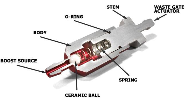
How does our PERRIN Manual Boost Controller work? There are 4 main components to it, the body, stem, spring and ceramic ball. Boost enters the body but is blocked by the ceramic ball. The spring behind the ball keeps the boost from getting past the ball. Adjusting the tension on the spring adjusts when boost pressure pushes the ball off its seat. When the ball moves off its seat, the boost flows through the boost controller and actuates the wastegate actuator. The ball simply delays when the boost gets to the actuator. The adjustment to when the ball lifts (effecting boost) is the tension on the spring. In our design, the stem gets screwed in and out of the body which changes the spring pressure on the ball. One key thing to our MBC (Manual Boost Controller) is our bleed hole. In the stem is a bleed hole that serves 2 purposes. One is to relieve pressure from behind the ball, when the turbo is not making boost. If this wasn't there the wastegate would be stuck open after the first time it made boost. The second purpose is to bleed some of the volume of air flowing through the MBC. This helps with keeping a steady boost curve that doesn't drop off severely at higher RPM.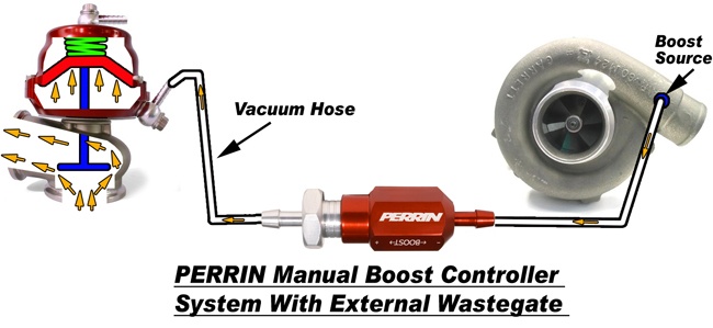
You can see the install is very simple. Hose in on one side and out the other! This above diagram is showing an external type wastegate, but same thing applies for an internal type wastegate. For most customers its about 10 minutes to install and a couple of good runs on the road to adjust. The downfall is there is nothing controlling the boost.
With a manual type boost controller there are some variables to the actual boost achieved. Temp out side, temp of the exhaust manifold, load on the engine all effect the actual boost level. This means from day to day, or even road to road, you can see a fluctuation in boost. For some customers, its not a problem as they have had their ECU tuned to account for the different levels. The problem is that your car can have varying performance, which not everyone likes. Also at part throttle, you can get get full boost (almost full power). This is also not a desired feeling as it removes some of the modulation of power. Most cars when stock are setup to deliver half the power at half the throttle. That way as you roll past half throttle, you add more boost/power, making the car more drivable. Power can be great, but if its like a switch, that can be hard to handle in corners!
Overall the Manual boost controller is cheap and easy to install, and its adjustable by anyone with a boost gauge. Those are great benefits for some customers, and a Manual Boost Controller shouldn't be overlooked when deciding how you should increase boost on your car.
Electronic Boost Control Solenoids
A solenoid is a simple valve that is mechanically opened (or closed) when battery voltage is applied to it. This is done using a coil winding surrounding a ferrous metal actuator. The battery voltage passes through the coil and causes a magnetic field which moves an actuator that pulls open a valve. Typically these are setup to bleed air from the hose going to the wastegate actuator. Keep in mind, the solenoid doesn't work as on off as describe, in fact the valve is turned on and off very fast to vary the amount of pressure bled from the hose. The speed and length the valve is opened, effects how much pressure is being bled off thus effecting boost. This process isn't self contained in the solenoid, but rather driven by the ECU (engine control unit) in your car, or sometimes by aftermarket controllers.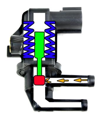
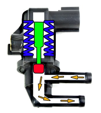
This above diagram shows a typical solenoid used for boost control at rest and also with voltage applied to it. The blue represents the coil that when engergized creates the magnetic field. The Green represents the ferrous metal, the red represents the valve being actuated and the orange arrows indicate the air flowing.
As mentioned above, the speed and length at which the ECU turns the solenoid on and off, effects the amount of air being bled and when the wastegate actuator actually opens. The ECU produces this pulsing (on and off) signal in based on tables in the ECU and many calculations. This pulsing signal is commonly known as the wastegate duty cycle. This duty cycle is a percentage of how long the solenoid is open for a given time. Because the solenoid can open and close only so fast, it has a normal operating frequency. The frequency is how many times it can operate in 1 second, referred to as hertz (not the rent a car company). Typically solenoids work in the 10-30hz range, but this is not what the ECU is changing to increase boost. Back to the duty cycle. The duty cycle is a calculated a percentage of time the solenoid is actually open. Meaning 50% DC (Duty Cycle) means the solenoid on for 50% of the time, and 100% means the solenoid is on all the time. The more time the solenoid is on, the more air is bled from the system, and in turn the longer the wastegate is delayed from opening.
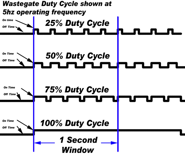
One second of time show above. This example shows a solenoid working at 5hz (turning on and off 5 times in 1 second) and then shows 25%-100% duty cycle. This allows you to visualize the amount of time the solenoid is actually open at different duty cycles. NOTE: the 100% doesn't show it operating 5 times in 1 second because its on all the time.
The ECU can vary this duty cycle signal to the wastegate solenoid to vary the boost higher or lower, to account for temp changes, atmospheric pressure changes, provide a steadier boost curve and even cut boost in situations when a failure has occurred. The ECU has many special maps/tables that determine the DC to use to control boost. This includes target boost tables, min and max DC tables, Boost error trim tables, air temp trims, speed trims gear trims and many more. The ECU uses these with a complicated algorithm to calculate duty cycle and then adjust it to reach its target boost. Here is an example of how this works and an example of the diffent typs of maps used to control boost.
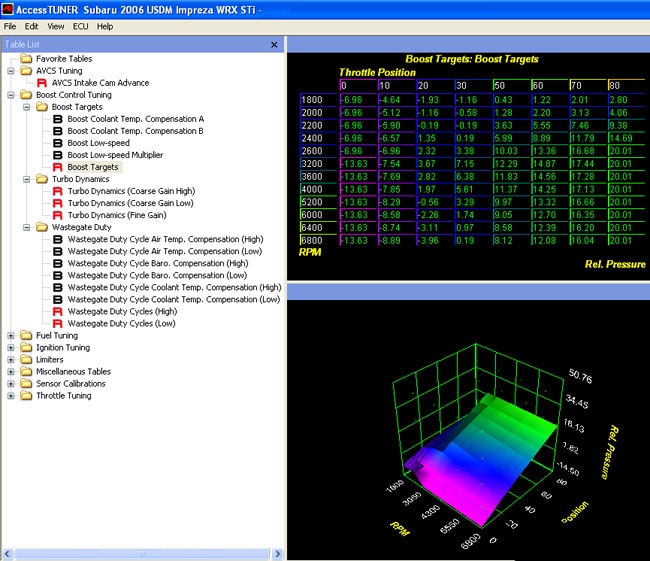
If the ECU sees the driver giving 70% throttle at 4000 RPM it reads a map that says it needs to hit 14psi. The ECU starts with a duty cycle of say 50%. Say it only hits 12psi at 50%, the ECU knows its off by 3psi and adds more duty cycle based on a boost error trim table. Say this equals 5% more duty cycle. Now its running 55% and the ECU is seeing 15psi of boost. Its still a bit high and using this boost error trim table it now pulls some duty cycle from the overall 55%. Lets say it removes 2% and now is at 53%. Now it hits its 14psi target and the ECU is happy until the boost starts to fall as the RPMS rise, or until the driver gives 100% throttle making for a new target boost. The calculations start all over again. This back and forth, and calculating happens many times a second to provide the engine with a steady boost curve. This is a very simple version of what actually happens. There are things like the time it waits to see if the calculated duty cycle actually worked, and start RPM's, gear ratio comps air temp trims, and many other things. This is a pretty complicated process but its what makes modern day turbo cars function so well with little turbo lag and all the safety features.
This duty cycle signal exists in all electronic boost control systems and is very important to understand in order to better use the PERRIN EBCS Pro solenoid.
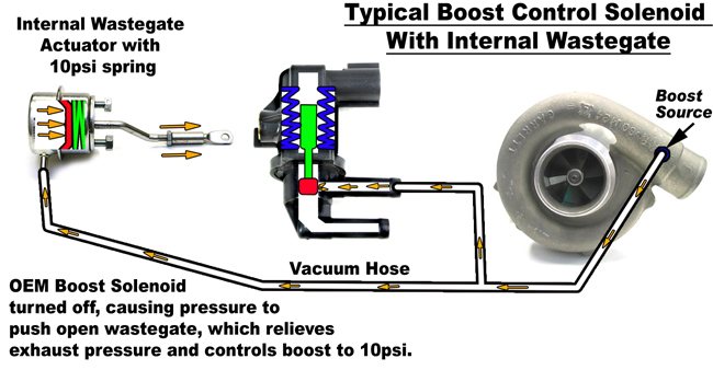
Above is a diagram of a typical OEM boost control setup using a typical 2 port solenoid. First is the system at rest with 10psi of boost coming from the turbo. At this point the solenoid is off and redirecting pressure to the wastegate making it open and in turn controlling boost to 10psi.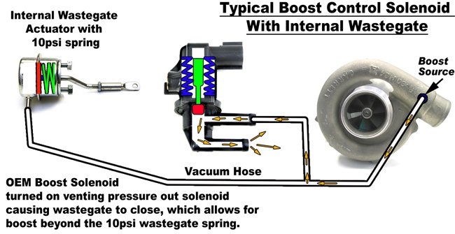
Now the solenoid is turned on bleeding pressure from the system. This in turn takes away the pressure that was pushing the wastegate open, and lets the wastegate close increasing boost pressure. Now imagine that happening all very fast on and off varying the degree at which the wastegate is actually open.
Below is an boost control system from a Subaru using the above diagrams as a reference. This shows a great example of a bleed type system that most all OEM's use. While it does work, its not the most efficient. All main parts of the boost system can be seen here, excetp the solenoid. The solenoid on most system is mounted somewhere off the turbo, and engine. Typically mounted to the chassis away from extreme heat.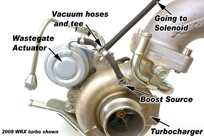
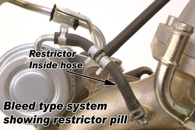
In OEM setups, like the one above, the wastegate duty cycle can get maxed out to 100% and still doesn't provide the desired boost. This means in some applications power is being held back because the solenoid can't do its job properly. In many OEM "bleed" applications this is remedied by using a restrictor in the hose coming from the boost source. This is put in place to limit the amount of work (Bleeding) the solenoid has to do. While a bleed type system can control boost, they leave a few things on the table that can be improved on.
One is boost response. The factory type 2port solenoid bleed type systems are always putting some amount of pressure on the wastegate actuator which means its already starting to open the wastegate (before it hits its boost target) and in turn loosing some turbo response. This may not seem like much pressure pushing it open, but you have to consider the exhaust pressure is also trying to push it open at the same time. The exhaust pressure can be double the boost pressure and also greater than the wastegate actuator spring. Which means even a small amount of pressure can start to open the wastegate and effect boost response. In some cars the exhaust pressure completely blows open the wastegate making for increasing boost nearly impossible.
Secondly a bleed type system may not be able to bleed enough air at higher RPM to reach the desired boost pressure. While changing the size of the restrictor can help this, its still a band-aid for a poorly working solenoid and poorly working system.
The good thing with these types of system is they are simple, only a few parts to install and go wrong not to mention they are cheap to make. Also if the solenoid fails it would default to the wastegate spring pressure for boost control. This safety aspect is important in all boost control systems and holds true with the PERRIN EBCS Pro. The PERRIN EBCS Pro (Electronic Boost Control Solenoid) utilizes 3 ports to control boost, which can be setup in many ways other than the stock "Bleeding" type system. This allows for better boost control, quicker response and more boost from your turbo! Find out how you can use a PERRIN EBCS Pro to get more power from your car by continuing to Part 3 of Boost Control Systems Explained.